
How to Power a Mobile Radio Safely in Your Vehicle
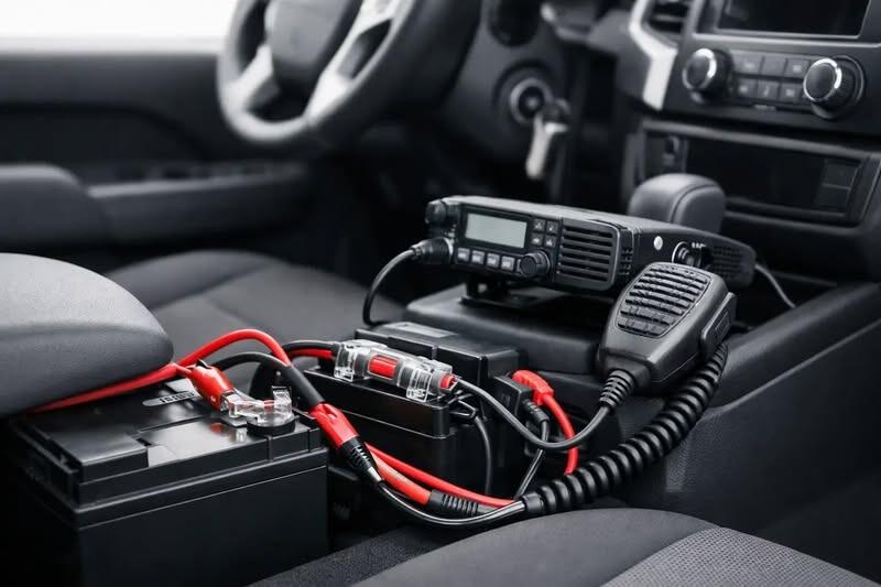
A mobile transceiver may look straightforward to install, but its power feed is where many otherwise good installations go wrong. A radio that cuts out on transmit, introduces alternator noise or, worse, has an unfused cable running through the vehicle is not a dependable communications setup. Knowing how to power a mobile radio safely means matching the installation to the radio's real current demand, the vehicle electrical system and the way the equipment will be used.
This guidance applies to most amateur, CB and professional-style mobile radios in 12 V negative-earth vehicles. Always start with the radio manufacturer's installation instructions, particularly where a supplied power lead, specified fuse ratings or a dedicated DC-DC converter are required.
Start with the radio's actual current requirement
Do not choose cable or fuses based solely on the radio's advertised output power. The relevant figure is its maximum current draw on transmit, usually stated in the specification as transmit current or current consumption at full RF power. A 25 W radio may draw several amps, while a 50 W VHF/UHF transceiver can commonly require 10 to 15 A or more at full output.
Receive current matters too, especially for a radio left monitoring for long periods. A modest standby draw can flatten a vehicle battery over time, particularly in cold weather or where the vehicle is not used every day. If the radio will be used for extended monitoring, assess the battery capacity, charging pattern and whether a low-voltage disconnect is appropriate.
Most mobile radios are designed for a nominal 13.8 V DC supply and will operate across a stated range around that figure. A vehicle battery is not a fixed 12 V source: voltage rises while charging and falls under load. Check that the radio is suitable for the expected voltage range before connecting it.
Do not connect a 12 V radio directly to a 24 V system
Lorries, some agricultural machinery and certain marine installations may use 24 V electrical systems. A standard 12 V mobile radio needs a properly rated 24 V to 13.8 V DC-DC converter, sized for the radio's maximum transmit current with sensible headroom. Taking a feed from one battery in a 24 V battery pair can cause charging imbalance and is not a suitable workaround.
Take the main supply from the battery
For most fixed mobile-radio installations, the preferred approach is a dedicated positive and negative cable run directly to the vehicle battery. This provides a stable supply path, reduces the chance of voltage drop on transmit and avoids sharing a marginal circuit with vehicle accessories.
Using an existing accessory socket, cigarette-lighter plug or an unknown dashboard feed may be acceptable for a low-current temporary installation, but it is rarely the right solution for a higher-power transceiver. Those circuits can have light cable, unsuitable connectors, shared loads and ignition-controlled operation that does not match the radio's intended use.
A direct battery connection also makes fault-finding clearer. If the radio has a clean, correctly fused supply but still suffers from interference or low voltage, the rest of the installation can be checked methodically rather than guessing which vehicle circuit is involved.
Choose cable for current and cable length
Cable needs to carry the required current without excessive voltage drop. This is especially significant where the battery is under the bonnet and the radio is mounted in a rear load area, cab or boot. A cable that appears adequate over one metre may be unsuitable over five or six metres.
Use good-quality stranded automotive cable with insulation suited to heat, oil and vibration. For many 50 W mobile radios, 2.5 mm² cable is a sensible minimum for a typical vehicle run, but larger cable may be needed for longer routes or radios with greater current demand. The radio manual and cable manufacturer's current-rating data should guide the final choice.
Avoid extending the manufacturer's supplied lead with thin wire, loosely twisted joints or household cable. If an extension is necessary, use a properly crimped or soldered connection, protect it with heat-shrink sleeving and keep the cable size consistent with the full length of the run. Poor joints create resistance, which becomes heat and voltage loss when transmitting.
Fuse both conductors close to the battery
A fuse protects the cable, not merely the radio. If the positive lead chafes through and contacts vehicle metal, an unfused battery cable can carry extremely high current. Place the positive fuse as close to the battery terminal as practical, ideally within a few centimetres.
Where both positive and negative leads run directly to the battery, fuse both conductors near the battery. This is the arrangement supplied or recommended by many radio manufacturers and provides protection if either lead is damaged or if there is an unexpected fault in the vehicle's earthing arrangement.
Use the fuse rating specified for the radio's power lead. Do not fit a larger fuse simply because the original one blows. A repeated fuse failure is evidence of a fault that needs investigation, such as reversed polarity, a trapped cable, a damaged lead or an internal radio problem.
Keep spare fuses of the correct type and rating in the vehicle. If you are fitting an additional distribution block for more than one device, each outgoing circuit should have its own appropriately sized fuse rather than relying on one oversized fuse at the battery.
Route and protect the power cable properly
A sound electrical design can still fail if the cable route is poor. Run power leads away from exhaust components, heater ducts, sharp brackets, steering mechanisms and areas where trim or seats can crush them. Use existing cable routes where practical, but do not bundle the radio supply tightly with sensitive vehicle data wiring unless there is no alternative.
Where a cable passes through a bulkhead or metal panel, use a suitable rubber grommet. Never push cable through a bare drilled hole. Secure the run at regular intervals with suitable clips or ties so vibration cannot wear the insulation against metalwork.
Take extra care around airbags, seat-belt pretensioners, pedals and steering-column components. Do not route wiring across airbag deployment paths or attach it to factory safety-system looms. On modern vehicles, consult vehicle-specific information before removing trim or working near battery-management sensors.
Before working at the battery, switch off the radio and vehicle ignition. Disconnecting the negative terminal first reduces the risk of accidentally shorting a tool between the positive terminal and bodywork. Be aware that some vehicles may lose settings or require procedures after battery disconnection, so check the vehicle handbook where necessary.
Understand the difference between DC negative and RF earth
For the radio's DC supply, a direct negative return to the battery is usually preferable to relying on a random bodywork point. A body earth point can develop resistance through paint, corrosion or poor fixings, causing voltage drop and intermittent operation.
That does not mean vehicle bodywork is irrelevant. The antenna mount and vehicle metalwork often form an essential part of the RF system, particularly for a conventional mobile antenna that needs a ground plane. A poor antenna bond can affect performance, increase RF feedback and make interference harder to diagnose. Treat the power return and the RF installation as related but separate parts of the job.
If alternator whine or ignition noise is present, do not assume a filter is the first answer. Check battery connections, cable routing, antenna bonding and vehicle charging-system condition first. Noise suppression components can help in specific cases, but they cannot correct a loose terminal or undersized supply cable.
Decide whether the radio should be permanently live
A battery-connected radio can be used with the ignition off, which is useful for amateur radio, monitoring and operational communications. The trade-off is standby current and the risk of leaving the set on. Some radios offer an ignition-sense lead or controlled power function, allowing the main supply to remain at the battery while the radio follows the ignition state.
For a radio that must only operate with the vehicle running, use a correctly rated relay or manufacturer-approved ignition-sense arrangement. Do not run the full radio current through a light dashboard switch or a small accessory circuit. The switch should control the relay or sense input, while the main fused cable continues to carry the radio load safely.
Test the installation under transmit load
Once connected, inspect the installation before fitting trim back into place. Confirm polarity with a multimeter at the radio-end connector, then check that the fuses are correct and cable runs are secure. Only then connect the radio.
With the engine running, monitor supply voltage at the radio while transmitting at the intended power level. A small voltage change is normal, but a significant drop points to cable resistance, poor terminals or an inadequate connection. Test on the frequencies and modes you expect to use, as longer transmissions reveal problems that a quick microphone check may miss.
Check for heat at fuse holders, connectors and joints after several transmissions. None should become noticeably hot. Finally, test vehicle functions affected by the work: lights, wipers, charging warning lamps, steering controls and, where applicable, reversing sensors or cameras.
A safe mobile-radio power installation is not about adding the most accessories. It is about a correctly sized, fused and protected supply that remains reliable when the radio is working hardest. If the vehicle layout, radio current draw or electrical system creates uncertainty, Radioworld UK can help identify the right installation components and a practical route to a dependable setup.
Go Back